

Home: Shells and Grenades
Please Note: Not all of the objects on this website are on display at the museum.
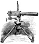
Hiram Maxim and the Machine Gun |
Spin It - What makes a Rifle work? |

Larger image |
CZECHOSLOVAKIAN VERSION OF TELLERMINE PT-Mi-K (practice) Czech version of German Tellermine. Date unknown. Originally thought to be Russian and kindly identified by Steve Diablo. See Comment. View 1 comment about this objectA1445 |

Larger image |
BLENDKORPER 2H SMOKE GRENADE Blendkorper 2 H Used by the Germans as a smoke screen before attaching mines to oncoming Tank tracks among other uses. A1442 |

Larger image |
WWII GERMAN SECTIONALISED 37MM ROUND AZ39, 1938 German WW2 round with impact fuze and cut away to show workings. The round is dated 1938 and was cut in half in 1984, probably for training purposes. Be the first to write a comment about this objectA0472 |

Larger image |
WW1 BRITISH BATTYE BOMB, 1915 In late 1914 and early 1915 Captain B C Battye of the Royal Engineers designed and put in to production through the Bethune Ironworks his 'Battye' or 'Bethune' bomb. A0961 |

Larger image |
WW1 CITRON FOUG or LEMON GRENADE, 1915 The fuze body was made of wood, holding a striker, creep spring, primer and safety fuze with a detonator. The fuze was covered by a safety cap that Has several shapes, this is missing. A0962 |

Larger image |
WWII PROXIMITY FUZE (FUSE) During the raids of WW2 a gunner issued complaints against our methods of defence, it was said, that shooting down an aircraft at night was "like shooting a fly in a darkened room with a pea shooter''. The Marconi Osram Valve Company amongst others, were given the task of solving the problem. Guided Missile technology was not an option at this time (the Germans astounded the world, later in the war with their V1 & V2). It was decided that a shell fuze, which triggered when an object was in the proximity of the shell (such as an aircraft), was the solution. The biggest problem was how to protect the amplifier section of the fuze from the blast of the gun. Special valves were developed to solve the problem; these can be seen in the 2nd section of the display. On leaving the gun at 20,000g and spinning at 3,000 rpm together with the vibration of the barrel, the success of these fuzes was no mean feat. Tests fired the fuze 8 miles into the sky vertically. On returning to the ground it had to be dug from under 8 feet of Salisbury Plain, amazingly it was still working. The amplifier is in the base, this was connected to the battery which was made of ring shaped plates around an ampoule of acid, upon firing of the gun the ampoule shattered and soaked the plates turning them into a charged battery. The top is a pointed cone and a plate embedded in plastic, this formed a capacitor which oscillated at 100mghz, if an object came close to this (up to 30ft) the oscillation was disturbed and the final valve triggered the detonator. The valves are oscillator, amplifier and trigger valve. Although the final product was produced and tested (over the channel so if it failed to explode it could not fall in to enemy hands), it needed to be produced in vast numbers; our manufacturing capability was saturated with weapons and planes at the time so the project was passed to the Americans. At the same time Radar was now becoming a reality and this unit was scrapped in favour of a device that used the new technology. Many of these and the new version were instrumental in bringing down the V1 ''Doodlebugs'' during the war. View 1 comment about this objectA0478 |

Larger image |
WWII PROXIMITY FUZE (FUSE) Developed by the British, production was taken over by the U.S. during WW2. They produced many of these fuses that worked by exploding only when they came into the proximity of another object. The method of detection used the new Radar method, possibly without Ranging developed during the war, although the original British design worked on another principal, (see Item No A0478). The advantages of these shells helped bring down many of the V1 rockets that were difficult to hit with conventional weapons. For a possible Valve see Item A1425. Be the first to write a comment about this objectA0430 |

Larger image |
WW1 FRENCH EXPERIMENTAL GRENADE Sold to the museum as an experimental French grenade. It measures 66mm diameter and 75mm high. No more is known about its origin, it may not be French and it may not be experimental, as during WW1 soldiers on the front line were coming up with all manner of ideas for new explosive devices. View 2 comments about this objectA0445 |

Larger image |
WW1 MILLS No. 5 GRENADE WITH No. 23 BASE AND LAUNCHING BRACKET The bracket was fitted to the end of a Short Magazine Lee Enfield rifle and held a No23 Grenade which was fitted with a rod screwed into the base plate. A0448 |

Larger image |
WW1 No.5 MILLS GRENADE Designed by William Mills - a golf club designer from Sunderland - he patented, developed and manufactured the 'Mills bomb' at the Mills Munitions Factory in Birmingham, England in 1915. A1141 |

Larger image |
WW1 No. 5 BRITISH MILLS GRENADE 1916 1st COW (Coventry Ordnance Works). 75 Million Hand grenades were produced during WW1 Be the first to write a comment about this objectA0869 |

Larger image |
WWII CUT AWAY MILLS No 36 TRAINING HAND GRENADE Training aid for the Mills no 36 hand Grenade dated 1940. Inside can be seen the coil spring that is released when the pin is pulled out, this fires the percussion cap (not present) which ignites the fuze, this burns for the time required normally around 5 seconds, which then fires the detonator on the end, firing the main charge. 75 Million hand grenades of of the Mills type were produced during WW1. For more information see Item A1141 Be the first to write a comment about this objectA0447 |

Larger image |
WW1 GRENADE LAUNCHER No1 Mk1 of 1917 Mentioned first in 1917 for use with a No23 type grenade, fitted with a gas check plate and designated the No36 Grenade See Item A0809. The plate is required to contain the gases from the blank cartridge in the rifle, thus pushing it out of the cup releasing the grenades clip (the pin having been removed). Be the first to write a comment about this objectA0778 |

Larger image |
BRITISH No69 BAKELITE HAND GRENADE, 1941 Manufactured from 1940 to 1944 by De La Rue Plastics out of Bakelite moulding with a No 247 All-ways fuze. View 1 comment about this objectA1561 |

Larger image |
WW11 No. 36 GRENADE This No 36 Grenade is fitted with a flat gas check plate on the bottom, and is a modification to the No23 grenade. The plate is required to contain the gases from the blank cartridge in the rifle, thus pushing it out of the cup releasing the grenades clip (the pin having been removed). The unit is fired from a discharger cup or launcher Item A0778. The No36 left service in 1972 View 1 comment about this objectA0809 |

Larger image |
AMERICAN PINEAPPLE GRENADE WITH TRIP FUZE(FUSE), 1960's Mk 2 Grenade replaced by the M67 with smooth outer used in Vietnam. View 1 comment about this objectA0981 |

Larger image |
WWII BRITISH STICKY BOMB No74 Not adopted by the Army, this Bomb eventually found it's way to the Home Guard, with some sad stories of accidents. The first pin pulled would remove the covers exposing the sticky ball, the second pin pulled would arm the device requiring only that the bomb be let go. A0896 |

Larger image |
WW1 TOFFEE APPLE BOMB Launched by a charge from a tube, this bomb could reach 500 to 600 Yards with devastating effect. A0895 |

Larger image |
WW1 EGG GRENADES Egg Grenades were carried in bags on the shoulders of the German Infantry during WW1, being light, many could be carried by one man, a slight advantage over the British Mills Grenade, but less effective because of their small size. Be the first to write a comment about this objectA0451 |

Larger image |
WW1 VIVIEN BRESSIERE FRENCH RIFLE GRENADE, 1915 The "Vivien Bressiere" rifle grenade. Placed in a cup-holder attached to the end of the rifle and fired using a ball charge to propel the grenade and initiate the timed fuse, this clever design was imitated by the German rifle grenade of 1917. This particular example is in very good condition and complete with the top lead plug, bottom brass plug and detonator holder. View 1 comment about this objectA0823 |

Larger image |
GERMAN RIFLE GRENADE, 1913 Using a blank cartridge in the rifle the rod was put down the barrel and fired. The problem with this is that the grenade is primed and the fuse ignited as the projectile leaves the barrel, therefore if the grenade does not eject itself correctley it will still go off!. This problem was solved by the Hales grenade see Item A0444. On the end of this grenade is a plate used to slow down the travel of the devise, as usually the enemy trench was no more than a few yards away. Be the first to write a comment about this objectA0443 |

Larger image |
WW1 HALES No 3 MK 1 SHORT RIFLE GRENADE The Hales Grenade was the solution to the problem of the unit exploding in front of the rifleman, if the grenade flopped out of the gun in front of you instead of being launched towards the enemy once it had been primed there was nothing you could do to stop it from exploding. Frederick Marten Hale, in 1915 designed a fuse that could not explode until it was in the air at speed, it worked by a wind vane that once turned it would prime the grenade and trigger the fuze, which had an impact graze type, if it fell out of the rifle without travelling at speed through the air it could not explode. The manufacture of these grenades was difficult and expensive at the time, but for the safety and confidence it gave the user, it was worth it. View 1 comment about this objectA0444 |

Larger image |
Mk1 No35 RIFLE GRENADE, 1918 Rifle Grenade used during WW1 A Hales Grenade produced towards the end of the War. It is similar to a No24 Mk2 type. Range with 15 inch rod 350-380 yards with 11 inch rod 220-240 yards. A1541 |

Larger image |
WW1 GERMAN POPPENBERG JAM POT OR STICK GRENADE, 1915 Known as a Jam Pot or Potato Masher because of its shape this Grenade lasted until 1917 with later versions used in the Second War. This is the original 1915 design with a lever to ignite the fuze, this was held in with a safety pin, once removed the unit was thrown. It also had a belt clip on the side of the body. This sample is badly corroded, and the wooden handle is not original. A0449 |

Larger image |
WW1 KUGEL HAND GRENADE, 1915 The Kugel grenade Model 1913 (' Kugelhandgranate ') 2nd Model. 1915. A0822 |

Larger image |
WW1 DISC OR OYSTER SHELL GRENADE The German Discus or Oyster Grenade worked by a tube held in by the safety pin, once removed fell out when being thrown like a Discus, once the tube was out it enabled four plungers on springs to become free, these had pins on the end hovering over four detonators, when the unit landed the pins were thrown into the detonator(s) and the device exploded. The explosive is held between two sheets of moulded steel clamped together round the edges. Be the first to write a comment about this objectA0453 |

Larger image |
WW1 FRENCH BALL or BRACELET GRENADE, 1914 Used during the early part of WW1 when supplies of grenades were scarce, this style dated back over 100 years, based on a hollow ball filled with black powder and a flamable fuze, on this version the fuze and charge was slightly more sophisticated. Be the first to write a comment about this objectA0450 |

Larger image |
WW1 STOKES MORTAR, 1917 Having a grenade type clip and fuze at one end and a shotgun cartridge at the other, this bomb was dropped down a tube with a pin at the bottom, on hitting the pin the bomb was ejected by the cartridge the clip flying off after leaving the tube, the bomb would explode after the fuze time. Be the first to write a comment about this objectA0905 |

Larger image |
APDS ARMOUR PIERCING DISCARDING SABOT (CUT AWAY), 1970's Armour-piercing, discarding-sabot (APDS) A0833 |

Larger image |
WW1 FRENCH F1 GRENADE, 1915 The French F1 was similar in appearance to the failed US grenade. It has a hollow cast iron body, heavily grooved in a familiar quilted "pineapple" pattern to enhance fragmentation. Although initially deployed to French forces in 1915 with a match primer it was soon replaced with a weather proof strike primer. This system required the soldier to strike a blow to the cap of the grenade after removing a safety cover to initiate the burn time fuse. Better than a match lit fuze, it still had to be thrown once the striker has been activated. The quest for a better fuze continued so that by 1917 there were a dozen or so contraptions developed as fuses for the French F1 Defensive Grenade. They included tumblers, pins, strikers, slow burn matches, each inventor claiming superiority. Be the first to write a comment about this objectA0821 |

Larger image |
WWII GERMAN GLASS MINE 43 Information about these mines is scarce as not very many were made, in fact it is possible that the glass portion of this unit is reproduction, however the fuze and plate are genuine probably the only surviving parts of the original. Being made of glass and used as an anti personal device it would be difficult to detect by normal mine detection equipment, it worked by breaking the glass cover when trod upon. Inside this unit is a dummy charge made to look like the original explosive. The Round Coloured glass disc sat on top of the thin sheet of glass over the trip to weigh it down. Known as the Glasmine43. View 4 comments about this objectA0431 |

Larger image |
(POST) WWII BAKELITE TELLERMINE , 1950's This model is made entirely of Bakelite to evade Mine Detectors, and was produced after the War. No other information is known. A0830 |

Larger image |
WWII 3.7cm RODDED ANTI-TANK BOMB Designed during WW2 as a stopgap for an improved anti-tank weapon that would fit the 3.7cm PAK (panzerabwehrkanone) 36 anti-tank gun, which was already in service, this weapon was not effective against the Russian T-34 Tanks. It was better to developed a new projectile than a whole new gun, it was known as the 3.7cm Stielgranate 41 or the 3.7cm Aufstek Geschoss (Attached projectile). This is a hollow charge weapon designed to penetrate thick armour by exploding just above the surface of the target, and melting a hole by using a shaped charge. Fitting into the barrel of the PAK36 gun and fired using a blank charge inserted in the breach. Weighing 8.6kg (19lb) with an effective range of 300m (328yds) it could penetrate 180mm (7inch) of armour plate. Be the first to write a comment about this objectA0832 |

Larger image |
WW1 CLARK 'D' GAS BOTTLE A German Gas Bottle which contained toxic gas to be used in the chemical Warfare during 1917. This green glass bottle contained a fluid with a colour varying from eggwhite to brown/yellow and a smell similar to shoe polish, it was known to the Germans under the code name 'Clark' which stood for DA-gas, a Vomiting agent. The product was meant specifically to penetrate through safety measures such as gasmasks, especially treated cloths and even the anti gas ointment Item A0819. It was only loaded into projectiles of the 7.7cm model 1896 and the model 1915. These could be identified by a blue cross on the body. When the shell exploded, the glass was shattered and the fluid vaporised. Tens of these formed a vast cloud of toxic gas. This was a very rare item as it was only to be removed when opening a gas shell, something that no reasonable human being dared to do. In 2002 during earthworks in the village of Houthulst (Belgium) near to the site of the Bomb Disposal Base of the Belgium Army, a dump of inner parts of all sorts of German Shells and grenades was discovered. Research has shown that in 1919 German prisoners of war had been put to work emptying these dangerous beasts to salvage steel. The parts not wanted were simply thrown into shell holes. Only around 300 are known to have survived from that source. Be the first to write a comment about this objectA0828 |

Larger image |
WWII INCENDIARY BOMB Incendiary bombs, also known as firebombs, were used as an effective bombing weapon in World War II. The large bomb casing was filled with small sticks of incendiaries (bomblets), and designed to open at altitude, scattering the bomblets in order to cover a wide area. An explosive charge would then ignite the incendiary material, often starting a raging fire. The fire would burn at extreme temperatures that could destroy most buildings made of wood or other combustible materials (buildings constructed of stone tend to resist incendiary destruction unless they are first blown open by high explosives). Originally, incendiaries were developed in order to destroy the many small, decentralized war industries located (often intentionally) throughout vast tracts of city land in an effort to escape destruction by conventionally-aimed high-explosive bombs. Nevertheless, the civilian destruction caused by such weapons quickly earned them a reputation as terror weapons (e.g., German Terrorflieger) with the targeted populations, and more than a few shot-down aircrews were summarily executed by angry civilians upon capture.The Nazi regime began the campaign of incendiary bombings with the bombing of London in 1940/41, and reprisal was exacted by the Allies in the strategic bombing campaign. In the Pacific War, during the last seven months of strategic bombing by B-29 Superfortresses in the airwar against Japan, a change to firebombing tactics resulted in some 500,000 Japanese deaths and 5 million more made homeless. 67 of Japan's largest cities lost significant areas to incendiary attacks. The most deadly single bombing raid in all history was Operation Meetinghouse, an incendiary attack that killed some 100,000 Tokyo residents in one night. A0808 |

Larger image |
BOFORS 40mm PRACTICE ROUND, 1951 Practice round for a 40mm Bofors Gun 1951. View 1 comment about this objectA0473 |

Larger image |
WWI WICKER SHELL CARRIER (BASKET) A Shell Carrier used during WW1 for the transportation of large shells (15cm), horses were used to carry these, sometimes as many as four on either side of it. View 2 comments about this objectA0349 |

Larger image |
WW1 HOWITZER 4.5 PROJECTILE WITH No101 FUZE (FUSE) Probably picked up from the original battlefield and repainted. Yellow Denotes a filling of High Explosive (HE), in this case Amatol . It is fitted with a No101 MK2 percussion (impact) fuse, has no safety shutter and no 'Graze' facility i,e, it only explodes when hitting an object, not if it grazes it. The only safety feature are pins that must be removed before loading into the breach. See Item A0867 for a description of the No101E fuse. Be the first to write a comment about this objectA0467 |

Larger image |
WW1 HOWITZER 4.5inch PROJECTILE WITH No83 Mk2 FUZE (FUSE) Shell probably picked up from the original battlefield and restored. Repainted in black denotes a Shrapnell shell with various explosive fillings. It is fitted with a No 83 Mk2 timed and percussion fuse. This fuse operates as follows:- A ball is released by centrifugal force on leaving the gun, this arms the percussion portion of the fuze. The timed portion set by the adjustable ring before loading into the breach ignites on leaving the gun, if the timed portion should fail to trigger the detonator, the percussion element will trigger the charge on impact or 'Graze' (skimming an object or surface). A safety pin is removed before loading the round into the breach. The No83 Fuze is similar to a No81 Fuze. See Items A0360 and A0361 Be the first to write a comment about this objectA0466 |

Larger image |
WW1 18 POUND HIGH EXPLOSIVE ROUND WITH No100 FUZE (FUSE) High explosive 18 pound round with No 100 impact fuze of 1915. The No100 fuze was replaced by the No101 type which had improved safety features. for more information see Item A0467. View 1 comment about this objectA0471 |

Larger image |
WW1 18 POUND SHRAPNEL ROUND Shrapnel shell with timed fuze unmarked. Designed to explode in the air above infantry, the charge inside, after the fuze timed out, was detonated at the base of the projectile, pushing the contents (Iron Balls) out at a high velocity and blowing off the fuze, as the projectile is now upside down (falling from the sky) these are projected toward the enemy. Be the first to write a comment about this objectA1542 |

Larger image |
WW1 SHRAPNEL 13 POUNDER INSIDE EXPOSED Shrapnel shell with timed fuze unmarked. Designed to explode in the air above the infantry, the charge inside (after the fuze timed out), was detonated at the base of the projectile, pushing the contents (Iron Balls) out at a high velocity and blowing off the fuze, as the projectile is now upside down (falling from the sky) these are projected toward the enemy. Fired from a 9cwt artillery Gun. View 1 comment about this objectA0470 |

Larger image |
WW11 KEY FOR OPENING AMMUNITION BOXES. This tool was used for opening ammunition boxes or powder cases, this was originally thought to be a fuze setting tool. Thanks to the commenter's who corrected this error . View 1 comment about this objectA1443 |

Larger image |
WW1 KEY FOR OPENING AMMUNITION BOXES. This tool was used for opening ammunition boxes or powder cases, this was originally thought to be a fuze setting tool. Thanks to the commenter's who corrected this error . View 2 comments about this objectA0900 |

Larger image |
WWII S.O.E.TIME PENCILS IN BOX Special Operations Executive A0982 |

Larger image |
WW1 HALES No 2 Mk 1 HAND or MEXICAN GRENADE A variation on the Hales Patent Grenade patented by Martin Hale who worked for the Cotton Powder Co at Faversham Kent, it is a simple percussion type with internal graze fuze. It was filled with 'Tonite', an explosive made of Gun cotton and Barium Nitrate. In 1907 the Cotton Powder Co tried to sell there design to the British Army but were rejected during trials of the No1 Type. The company sold it to the Mexican Government with a 7mm rod for firing from their rifles. During WW1 shortages of the No1 grenade, the British purchased supplies from Mexico. The design was modified removing the rod and fitted a handle and tape for throwing, this was the NO2 Mk1. The Detonator is inserted, the streamer unfolded and the safety pin removed, (not shown) thrown high into the air to allow the tail to point the unit head first when hitting the ground. The No2 was introduced in Feb 1915 and declared obsolete in 1920, about 130,00 were manufactured. View 1 comment about this objectA1292 |

Larger image |
WW1 RACQUET GRENADE WITH BATTYE BOMB The French magazine L'ILLUSTRATION 22 May 1915 shows a picture of a soldier in a trench throwing one of these and the title refers to it as a 'Racquet' bomb. A0454 |

Larger image |
WW1 BRITISH No12 Mk1 (HAIRBRUSH) GRENADE This No12 Mk1 commonly known as a Hairbrush grenade is almost certainly a reproduction not original. A1036 |

Larger image |
WW1 FRENCH ERSATZ HAIR BRUSH GRENADE Home made Grenade, made from a metal pipe and a piece of wood, common when stocks of manufactured grenade were scarce. A1000 |

Larger image |
WWII GERMAN MODEL 24 'STIELHANDGRANATE' Hand grenade known as the 'Jam Pot' or 'Potato Masher'. Used by the German army form the end of WW1 through WW2.[Reproduction] A1100 |

Larger image |
WWII PRACTICE SMOKE HAND GRENADE, GERMAN German practice smoke hand grenade, this grenade would be used to develop throwing techniques. [Reproduction] Be the first to write a comment about this objectA1101 |

Larger image |
WWII BUTTERFLY BOMB, Sprengbombe Dickwandig 2kg or SD2A Stored in containers within an aircraft carrying up to 108 bombs folded, when released from the container the wings opened and rotated the shaft out of the bomb thus arming it, also as the bomb fell the wings stabilized its fall and gave the appearance of a butterfly, hence the name. A0987 |

Larger image |
WWII GERMAN BUTTERFLY BOMB There is a hole in the bottom of the unit, where the explosive ware removed, the drouges (wings) were never actually used on this version. It seems to have been made up from odds, as the cylinder is a screw type. A0365 |

Larger image |
WWII BRITISH SHELL FUZE (FUSE) COVER Shell covers were used to protect the fuze during transit, and in the early days of the war were kept and reused. This cover is marked as a souvenir possibly for the Fusiliers, Royal Artillery, or Royal Engineers. A0435 |

Larger image |
WW1 BRITISH IMPACT FUZE (FUSE) No 13 Mk 5 AND COLLAR or PLUG Impact Fuse No13 Mk5 and collar or plug for unknown projectile, it is not certain if the two objects go together. The No13 Fuze was a direct action impact type in use in 1915. Used with heavy common Lyddite shells. The charge will only detonate on impact, and there is no safety feature other than pins removed before installing into the breach. View 3 comments about this objectA0437 |

Larger image |
WW1 GERMAN FUZE (FUSE) FOR 17cm MINENWERFER (TRENCH MORTAR ) Timed and Percussion fuze for the German 17cm Trench Mortar, the time delay is set with an adjustable ring that could be changed according to the calculations. It worked by igniting a ring of a slow burning compound underneath the calibration ring, the time it burnt before detonation was determined by the position of the ring. If the timing should fail then the percussion or impact part would take over. Be the first to write a comment about this objectA0436 |

Larger image |
WW1 DOPP 92 SP 15 GERMAN TIMED FUZE (FUSE) Double effect fuse, this model was an evolution of the Dopp Z 91, based on the same principles, therefore having a classic percussion system in the tail and a rotating discs time system in the upper cone. The lower disc mobile was engraved with graduations from 1 to 29 seconds, and a Roman cross for the pure impact percussion function. A0434 |

Larger image |
WW1 No. 100 BRITISH FUZE (FUSE) WITH CUT AWAY Impact fuze used during WW1. This version has been cut away to show the workings, and was used for training. It is similar to the Fuze No101, has no safety shutter or bolt, the only protection from premature ignition were the pins removed before loading into the breach. A0433 |

Larger image |
WW1 No 106 Mk 2 IMPACT FUZE (FUSE) Impact fuze for Howitzer 4.5'' Projectile, The original fuze did not have a safety shutter, but the 106E type did. The shutter armed the fuze by revolving at speed. At the front is a plunger to trigger the device, which is further protected by a collar and weight, which is spun off in flight. A0469 |

Larger image |
WW1 4.5 INCH HOWITZER CARTRIDGE CASE Cartridge case for Howitzer Gun, the projectile portion was fed into the Breach of the gun first, followed by the charge rapped in cloth, then on top of that the cartridge casing containing the percussion cap was fitted over the charge and pushed up to the rim. A0361 |

Larger image |
HOTCHKISS 47mm 2.5lb REVOLVER ROUNDS, 1900's Supplied to the Japanese Navy for their Revolver ship mounted guns. Be the first to write a comment about this objectA0878 |

Larger image |
WW1 BRITISH 100/101E FUZE (FUSE) No101 MK2 impact or percussion fuze is fitted with a safety shutter which only opens when spinning at speed, it can also be fitted with a 'Gain' which has three more possibilities, not only does it have an additional shutter mechanism but can also be timed after impact. It also has a 'Graze' facility, which means it will still ignite if it skims a surface; the last feature is an extra charge for explosives than require more heat for ignition. A0876 |

Larger image |
WWII S.O.E ITEMS IN FRAME Special Operations Executive S.O.E. items such as Time pencils. Time pencils were fuzes timed by acid corroding a thin wire , when the wire broke a spring forced a pin onto a percussion cap exploding a small charge. A0810 |

Larger image |
WWII ANTI PERSONAL MINE FUZE (FUSE) Not clear how this worked, as the prongs are fixed and the pin will not enable operation as aperture below is blocked. A0983 |

Larger image |
1871-1900 MARTINI HENRY ROUNDS, 1900's Originally all Martini rounds were hand made out of brass foil with a steel base holding the cap, problems were common because of the fragile casing jamming in the breach. The problem was overcome on June the 9th 1885 with the adoption of the new drawn brass case. A0439 |

Larger image |
SNIDER BOXER CARTIDGE AND PELLET, 1800 Boxer cartridge showing the internal pellet that expands the projectile when fired into the rifled barrel. A0543 |
Back to top


