

Home: Telegraphy
Please Note: Not all of the objects on this website are on display at the museum.
|
Telegraphy from the Greek words tele = far and grahein = write, is the long distance transmission of messages electronically, eventually involving the use of Morse Code. |
A Brief History of Telegraphy |

A Short History of the Galvanometer |

Larger image |
EARLY MORSE KEY, 1910 Early Morse key, not dated but marked Marconi. A0236 |

Larger image |
WWII BUG OR PADDLE MORSE KEY, 1942 Known as a 'Bugs' key and originally developed as the 'Vibroplex' or semi automatic key. A0250 |

Larger image |
WWII WAR DEPARTMENT PRACTICE MORSE KEY Training key for the Air Ministry View 2 comments about this objectA0248 |

Larger image |
WWII BAUMUSTER (GERMAN) MORSE KEY Morse key for equipment unknown View 3 comments about this objectA0249 |

Larger image |
GAMAGES MORSE KIT AND BUZZER, 1940's Bought as a toy for youngsters and adults to learn or practice Morse. A0251 |

Larger image |
WWII AIR MINISTRY ENCLOSED MORSE KEY TYPE D Used on the high voltage portion of circuitry in a transmitter, therefore the unit is fully enclosed to protect the operator. View 7 comments about this objectA0245 |

Larger image |
MUSONIC OR TOY MORSE TRAINING KEY, 1940's Either a toy for learning Morse or simply a training aid, it could be used as a simple local sounder, or connected to a line with another remote unit. Be the first to write a comment about this objectA0780 |

Larger image |
SPEED MORSE KEY, 1950's Key known as a 'speed' key, the familiar shape had nothing to do with increasing the operator speed, just a selling point. View 2 comments about this objectA0724 |

Larger image |
LARKSPUR MORSE KEY K MK 3, 1950's Morse key for use with the Larkspur range of Transceivers made by Pye after WW2. View 1 comment about this objectA0244 |

Larger image |
MORSE KEY WITH LAMP, 1950's The bulb with this key can be used for training by sending without the need for wires. A0960 |

Larger image |
'SPEED' TYPE MORSE KEY JAPANESE, 1960's The name 'speed' is loosely used and in fact this style of key is not a 'speed' Key . It was common for manufacturers to abuse the name which refers to a totally different type of key. This item made in Japan. A0723 |

Larger image |
POST OFFICE GULSTAD 304 RELAY, 1900's The Gulstad Relay was invented by K.Gulstad of Copenhagen in 1898 A0238 |

Larger image |
POST OFICE RELAY 'B' No 14802, 1920's Relay used in telegraphy acting as a form of amplifier for the signal, sensitive coils moved the contacts which controlled equipment that could be powered locally. A0278 |

Larger image |
POST OFFICE RELAY 'B' No 5462, 1920's Odd version marked as 'B' but more like a 'D' relay, for information on Telegraphy relays see item A0252. it has a single throw contact is non polarised (no magnet) has only one coil, with no other markings. A0277 |

Larger image |
POST OFFICE RELAY TYPE G, 1920's Used in telegraphy systems to amplify power and and enable equipment to be powered locally. Post Office Relay 'G' on a pluggable base. A0253 |

Larger image |
POST OFFICE RELAY TYPE B No 9534, 1920's Relay used in telegraphy acting as a form of amplifier for the signal, sensitive coils moved the contacts which controlled equipment that could be powered locally. Post Office Standard Relay 'B' A0252 |

Larger image |
POST OFFICE RELAY TYPE B No 7938, 1920's Used in Telegraphy to amplify the power lost on long cables, by activating a sensitive coil which moves contacts that operate equipment powered locally. Post Office Standard Relay 'B' taller version. A0254 |

Larger image |
SIEMENS GIANT TELEGRAPH RELAY, 1930's Hermetically sealed (watertight) Large Telegraphy Relay in Brass container. Be the first to write a comment about this objectA0774 |

Larger image |
GPO REVERSING RELAY, 1950's Relay used for reversing polarity of lines, made from an old Morse sounder. A0081 |

Larger image |
BRITISH RAIL RELAY, 1957 Originally sold at the BT museum auction . A0082 |

Larger image |
WW1 MORSE KEY AND SOUNDER, 1916 Morse sending and receiving station. On the side of the unit (out of view) is a standard P.O jack No8 for Telephone plug No406, possibly for a headset, or even a telephone line. A0231 |

Larger image |
GAMAGE TRAINING KEY or MORSE STATION, 1930's Made for training amateur radio enthusiasts. Not to be considered as a toy more a training aid. A0889 |

Larger image |
ABC TELEGRAPH COMMUNICATOR TESTER, 1850's The ABC telegraph was an early form of communication where an arm was turned to a letter sometimes by a pulse, and sometimes by buttons opposite each letter, the arm being held by a return spring and latched on the letter required, a button was pressed releasing the arm which returned back to the beginning sending a number of pulses relating to the letter chosen i.e. the letter C would give 3 pulses the letter B would produce 2 pulses. The receiving unit would be driven by an internal solenoid counting the arm up to the required letter, after each letter was sent it was necessary to reset the unit and start again, sometimes this was achieved automatically. Such units were used while Morse code was being devised, around the 1840's, and continued in some countries long afterwards. This unit was simply a testing device for checking received signals only. Be the first to write a comment about this objectA0232 |

Larger image |
L.DOIGNON CHARACTER PRINTER , 1880's The printer used Baudot's 5 bit code, using five telephone lines, to receive a signal that could be printed on a strip of paper. It was all driven by an electric motor. On receipt of a start signal the five bit code would latch five solenoids that would enable the mechanism to print a character by turning the wheel and engaging the correct letter. After printing a character the solenoids released ready for the next one. A0234 |

Larger image |
BLICKENSDERFER TELEPRINTER No 5, 1890 This machine has been converted to a Teleprinter from the famous No5 machine, hence no keyboard. Instead are 5 solenoids with linkages to decode the 5 bit code into text. The whole machine is driven by a pulley connected to an electric motor (not present). A0756 |

Larger image |
CARPENDIER PUNCH TAPE READER, 1890's Punch tape reader for five bit Baudot coded tape, as the tape is pulled through the trough five fingers are able to move upwards into the holes in the tape, contacts inside the unit detect this and pass on the information to other equipment. Be the first to write a comment about this objectA0235 |

Larger image |
DOUBLE PLATE SOUNDER, 1900's In the early days of Morse all railway stations were equipped with the new morse code technology. Hearing the clatter of a Morse receiver, known as a sounder, could be a problem in a noisy environment. A gentleman called Charles Bright invented 'Bright's Bells' in 1855, a crude version of the exampe shown here. A0227 |

Larger image |
POST OFFICE INKER No. 128, 1900's Inkers were used to print dots and dashes on to a strip of paper to enable easier reading; known also as a Direct Writer. This item uses a clockwork motor to drive the paper forward Be the first to write a comment about this objectA0242 |

Larger image |
ATM STOP START INKER, 1910's Morse Inker for recording dots and dashes on a strip of paper. A0243 |

Larger image |
NON-POLARISED MORSE SOUNDER, 1920's A simple Morse Sounder used for receiving Morse. It may have been made by Gamage who specialized in telegraphy equipment in the 1920's. Non polarized unit similar to a design used by the Post Office and purchased by those who wished to learn the 'Art' of Morse telegraphy. And indeed it was an art. Morse code requires very high skills, strange that when it became adopted as a standard for communication by Samuel Morse in 1844 many other simpler forms of sending characters by wire were being developed, and yet Morse surpassed them all, probably because of the desire to improve or own a skill that others could not achieve, in today's world skills are avoided by modern computing. It was possible for the operator to distinguish whether the arm of the unit was up or down, by the different sound as the spaces between the dot or dash identified the end of a character, spaces between words could also be given as larger gaps, but most skilled operators omit this and join all the words up, making it important to write down what is heard immediately to avoid confusion. Be the first to write a comment about this objectA0887 |

Larger image |
POST OFFICE POLARISED SOUNDER, 1890's Receiving instrument for Morse code, invented by CC Vyle in the late 1800's and in use until the 1960's. A0229 |

Larger image |
WHEATSTONE NEEDLE TELEGRAPHY STATION, 1930's In 1851, Samuel Morse and his code was accepted around the world. (See 'A brief History of Telegraphy' above) A1235 |

Larger image |
SINGLE NEEDLE TELEGRAPH (WHEATSTONE NEEDLE), 1930's Information can be read if a needle is moved to the left or right. The single needle unit was a further development of Wheatstone and Cookes 5 needle system, which did not use Morse Code, and was replaced by the single needle system. This unit is clearly marked with the complete alphabet in Morse code on its face, and was probably used by the British Post Office. View 1 comment about this objectA0228 |

Larger image |
RAF MORSE INKER, 1930's Morse inker which transferred Morse Code into dots and dashes printed onto a strip of paper. A0233 |

Larger image |
GPO NON-POLARISED 20 Ohm SOUNDER, 1930's Post Office Polarised Sounder A0803 |

Larger image |
CREED 7E TELEPRINTER of 1931 Frederick George Creed was born in Canada and spent the early part of his life working on Morse equipment. He was convinced he could do better. He then moved to Scotland and developed a method of sending messages by text. Later he formed Creed and Company Ltd, and in 1921 they were at Telegraph House East Croydon. A0936 |

Larger image |
CREED TELEGRAM TELEPRINTER 47B, 1950's Used in Post Offices throughout the world for typing Telegrams. The Creed model 7 page teleprinter, whilst not the first A0098 |

Larger image |
TIN CONTAINING ROLLS OF GUMMED TAPE, 1950's Paper tape used in telegraphy machines, such as the Creed 47B item NoA0098. Not to be confused with punch tape, the paper is too narrow for this, the gum is used to stick it to the Telegram sheet. As it says on the tin! Be the first to write a comment about this objectA0531 |

Larger image |
G.P.O. No83 GALVANOMETER IN LEATHER CASE, 1930's GPO engineers Tangent Galvanometer in leather case Type No 83 maker unknown. View 1 comment about this objectA1527 |

Larger image |
SILVERTOWN TELEGRAPH WORKS GALVANOMETER, 1930's Used to detect current in either direction in Telegraph circuits on receiving or sending stations. Also used as test equipment and known as a differential type. Made at the Telegraph Works Silvertown. View 3 comments about this objectA1469 |

Larger image |
GPO 970 DIFFERENTIAL GALVANOMETER, 1930's Used to detect current in either direction in telegraph circuits on receiving or sending stations. In Differential mode two coils deflect the needle left or right; if the current through both coils is equal then the needle will remain central. A0239 |

Larger image |
POST OFFICE GALVANOMETER GPO 41, 1930's Used for indication of signal direction ( Current ) in telegraphy systems also as a test instrument. View 2 comments about this objectA0241 |

Larger image |
EDISWAN GALVANOMETER, 1930's Used to detect current in either direction in telegraphy systems. A0240 |

Larger image |
SILVERTOWN GALVANOMETER, 1916 Used as either a piece of test equipment or to send or receive Morse. A0328 |

Larger image |
TAT-1 TRANSATLANTIC CABLE , 1956 Section of a Transatlantic Cable TAT-1. It is of the coaxial type and was the first Transatlantic telephone cable laid in 1955 and 1956 between Gallanach Bay near Oban and Clarenville Newfoundland by the cable ship Monarch. Initially carrying 36 telephone channels, later increased to 48. The cable was last used in 1978 by which time it's capacity had risen to 72 channels using modern technology. This section was donated by Nortel (STC) with an attached note from their donator which reads, ''TAT-1 undersea cable. I rescued this section of cable from the System Planning Division when it broke up (sic). I didn't work on undersea cables myself & cannot give any information on it. I'm told that Geoff Farrinton might be able to help. Michael Beasley.'' A1790 |

Larger image |
GUTTA PERCHA PENCIL TRAY, 1880's The Gutta Percha Company was founded in Stratford London in 1885 by Henry Bewley and Samuel Gurney, eventually moving to Wharf Road London. Gutta Percha is a Latex substance and is also Thermoplastic, it originates from the Gutta Percha or Isonandra tree in Malaysia, like Rubber it is collected from the trees weeping exterior and processed into a hard black substance that can be formed into any shape required, when cooled it becomes hard and solid and was used in the making of many objects such as, drinking mugs, buckets or washing bowls, and other items. It was discovered by Michael Faraday that it was an ideal insulator of electricity and was subsequently used for undersea cables in 1850/1 continuing for the next 80 years until being replaced by Polythene in the 1930's. It is of interest to note that the first undersea cables failed due to many reasons, among them was that Gutta Percha was being eaten or damaged by living creatures (Teredos Marine worms), later cables were protected from this problem. See Items A0570-A0571-A0572- A0573-A1316 and A1317. A1788 |

Larger image |
THE GREAT EASTERN STEAMSHIP REPRINT OF 1860's, circa 1970 A Limited edition print of the Great Eastern Steam Ship. The original painting from which this is taken dates from the 1860's and was probably painted by Henry Clifford 1821-1905, a Telegraph Engineer who also served on this vessel. This limited edition could have been made anywhere between 1900 and the 1960's. Printed on the back: -. ''This reproduction is number 228 of an edition limited to four hundred and forty copies''. The original was in the possession of Sir Kenneth. G Corfield, Managing director of Standard telephones and Cables London.'' Kenneth Corfield was Director of STC from 1970 to 1985, so this print was probably commissioned during this period. Kenneth Corfield is better known for the 'Periflex' camera that he designed and introduced in 1953. See Item A1799. A1782 |

Larger image |
WIRELESS TELEGRAPHY LICENSE 1923, 1923 Paperwork relating to an application for a wireless license in 1923 under the Telegraphy Act of 1904 it was necessary to have a license to receive wireless messages by Telegraphy and a separate licence to transmit telegraphy messages. Francis Leslie Freeland was under 21 in April 1923 so his father had to apply on his behalf J.H.Freeland. The licence obtained was for the reception of telegraphy signals and also to experiment with equipment of his own. The Aerial had to be no more than 100 feet high and no more than 100 feet long; the use of a heterodyne oscillator directly connected to the aerial was not permissible between the hours of 9PM and 11PM weekdays and Sundays and not between the wavelengths of 300 to 500 metres. Also supplied at the time by the Controller and Accountant General Mr H.N. Bunbury of the General Post office was an application form for transmitting equipment. This does not appear to have been used. A1587 |

Larger image |
TELEGRAPH RELAY, 1899 Removed from the South Western House Hotel, built in 1830, by Peter Silett a radio engineer for Radio Solent. Identified as a telegraph relay, however the three contacts are too large for Telegraph Transmission, and it may have been used in a supervisory mode such as power control. Be the first to write a comment about this objectA1583 |

Larger image |
1965/6 TELEGRAMS, 1965 Two examples of machine printed tape on Telegrams. See Item A0098 in Sounders and Stations section. View 1 comment about this objectA0197 |

Larger image |
BRASS BASE SINGLE CORE CABLE, 1900's Single core Telegraphy cable with steel armour for under ground use. A0573 |

Larger image |
SINGLE CORE ARMORED CABLE, 1900's Early under ground or under water telegraphy cable. A0571 |

Larger image |
SAMPLE OF CABLE LAID BY GREAT EASTERN, 1865 The transatlantic telegraph cable was the first cable used for telegraph communications laid across the floor of the Atlantic Ocean. It crossed from the Telegraph Field, Foilhommerum Bay, Valentia Island, in western Ireland to Heart's Content in eastern Newfoundland. A1317 |

Larger image |
CENTRE SECTION OF 1st TRANSATLANTIC CABLE, 1860's The transatlantic telegraph cable was the first cable used for telegraph communications laid across the floor of the Atlantic Ocean. It crossed from the Telegraph Field, Foilhommerum Bay, Valentia Island, in western Ireland to Heart's Content in eastern Newfoundland. A1316 |

Larger image |
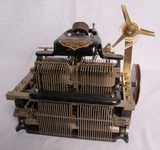
COHERER DEMONSTRATION BOARD, 1920's The first radio transmissions were made using a spark transmitter and a receiver known as a 'Coherer'. A1284 |

Larger image |
COMMUTATOR KEY, 1930's Polarity reversing key known as a "Commutator Key". A0237 |

Larger image |
TRANSATLANTIC CABLE IN PENDANT AND LETTER, 1866 Detail of Letter A0567 |

Larger image |
SINGLE CORE POST OFFICE TELEGRAPHY CABLE, 1900's Early armour protected cable for under ground use. Insulation may be Gutta Percha. Gutta percha was obtained from a variety of guttiferous trees throughout the Pacific Rim although different varieties produce materials of differing quality. The differences generally reflect the quantity of resin in the product with that from Pahang having the lowest resin content. Balata has one of the highest resin contents and was obtained from trees in the tropical regions of South America. A0572 |

Larger image |
4 CORE ARMORED TELEGRAPHY CABLE, 1900's Telegraphy cable heavily armoured and further protected with layers of hemp saturated in a water proof compound, for under sea use. It is possible of course that this could have been used for Telephony. Be the first to write a comment about this objectA0576 |

Larger image |
SINGLE CORE TELEGRAPHY CABLE, 1900's Early Telephone or Telegraphy cable possibly for under sea use. A0570 |

Larger image |
4 POLE SWITCH WITH PEGS, 1920's Early method of switching circuits using removable pegs. A0805 |

Larger image |
4 WAY SWITCH WITH CRANK, 1930's School Laboratory Switch supplied by Griffin & George for Universities and Colleges. Be the first to write a comment about this objectA0806 |
Further Reading (external sites):
Back to top


