

Home: Military Comms
Please Note: Not all of the objects on this website are on display at the museum.
Hiram Maxim and the Machine Gun |
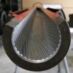
Spin It - What makes a Rifle work? |

Larger image |
GERMAN TELEPHONE EXCHANGE 10 LINE Known as a Small Flap Cabinet, or Klappenschrank in German (Clapboard). Switching is achieved by loose cords and plugs, with flaps on the front to indicate that a phone has been lifted, buttons on the front can select one circuit at a time presumably for the operators headset. Dated 1940. A1446 |

Larger image |
ELECTRONIC ENIGMA-E, 2009 Paul Reuvers and Marc Simons in the Netherlands decided to make this machine in 2001, after much research and overcoming many problems it was launched as a kit in 2003, it is much smaller than the real thing and is built around an original 4-rotor type machine. It does exactly what the original electro mechanical version did but using modern electronic components and software created by them. Two or more machine can encrypt and decode messages in the same way as the original. It has replaced the normal coding wheels with a led display and the patch board (Steckerbrett) on the front with normal links as in the original but with different plugs. Changing the days code would be done by up and down buttons above and below the LED display. The message to be decoded is entered on the keypad and the result of each key pressed is displayed momentarily on the illuminated panel above as in the original. A technical explanation of how the original machine worked together with all the variants that were produced. The idea was conceived in 1918 by German engineer Arthur Scherbius and Patented under the name Enigma in 1923 they were produced up to World War Two and used until the 1950's. In 1944 an addition was added known as the 'UHR' a 40 position switch which connected into the plug board. An electronic kit is also available for this unit. A1682 |

Larger image |
RACAL SPIKE ANTENNA, circa 1980 Ground spike for ten section aerial complete with lead and carrying case. Using the spike to create a ground connection transmission would be improved. By varying the length of the number of section of the aerial it can be matched during transmitting for 30 to 76 MHz. More sections are available out of the ten supplied for other frequency's. Be the first to write a comment about this objectA1667 |

Larger image |
SIGNAL LAMP/TORCH Possibly naval, because of the colour of the paint, at the end is a broad arrow, indicating that it was made for the war department, or government property. The lens is red but this can be removed to reveal a further clear glass lens inside to provide normal torch use. At the rear of the unit is a key that can be retracted for protection, providing a Morse signalling application. Underneath at the rear, is a bracket to provide stability when the key is in use. See Item A1601. Be the first to write a comment about this objectA1602 |

Larger image |
LEADS COUNTERPOISE No2 Mk2, 1950's No. 2 Mk II Counter-Poise for the Wireless Set No. 19 antenna, and similar. The Counter-Poise has four wire segments which are laid like a cross underneath the radiating antenna. The four wires terminate to a central location at the radios earth terminal to provide an artificial ground plane. Each wire segment is 340 Cm Long. A1518 |

Larger image |
HEADSET No10 PACKED, 1952 Headset No10 for the Wireless Set No19 in original packing, this item literally fell of the back of a lorry in 1952, and is dated April 52. for a view of the headset see Item No A0095 A1515 |

Larger image |
HEADSET No10 FOR WS19, 1950's One type of Headset and microphone used for the Wireless Set No19. Item A0088 and A0871, and WS62 Item A1405. View 2 comments about this objectA0095 |

Larger image |
WWII TYPE F FANY HEADSET, 1940's Headset used by The First Aid Nursing Yeomanry F.A.N.Y. as part of the S.O.E. Special Operations Executive. The First Aid Nursing Yeomanry was created in 1907 by Lord Kitchener, as a link organisation between front line fighting units and field hospitals. A0488 |

Larger image |
HAND PEDAL GENERATOR Mk810A, 1950's The Mk810A generator also known as 'Generating set AC 45W 110V, hand or pedal driven, No1 Mk1' was intended for powering AC powered equipment such as receiver Mk122 or Mk123. The unit can be pedal or hand operated, and is supplied with all the suitable accessories, on the top of the main unit is a meter indicating up to 150V with two red marks between which the needle should be held whilst turning the pedals. The base plate comes with a chain so it can be attached to a tree trunk or other similar object, also supplied are two clamps for table mounting. The whole unit and parts pack into the box supplied. A1461 |

Larger image |
WW11 CARRIER PIGEON MESSAGE TUBE Attached to the pigeons leg and containing a small rolled paper message, sometimes as thin as a human hair. A1295 |

Larger image |
WWII FANY MORSE KEYS Silent Keys used by The First Aid Nursing Yeomanry F.A.N.Y. as part of the S.O.E. Special Operations Executive. View 3 comments about this objectA0485 |

Larger image |
WWII SG BROWN HEAD SET War Department issue DLR headphones of WW2 made by S.G.Brown. View 1 comment about this objectA0752 |

Larger image |
WWII ADMIRALTY SIGNAL LAMP, 1944 Admiralty Pattern 378A signalling Heather type. Previously A1110 |

Larger image |
WWII MORSE TRAINING SET Morse Training set for War Department Wireless Operators View 3 comments about this objectA1098 |

Larger image |
WWII US SIGNAL CORPS MORSE KEY, 1943 Morse key from WW2 in original box. View 2 comments about this objectA1102 |

Larger image |
WWII BC221-M WAVEMETER Used for Calibrating wireless transceivers. 125KHz to 20MHz heterodyne frequency meter with individual calibration book and internal Xtal calibrator. A0102 |

Larger image |
CALIBRATOR CRYSTAL No10 , 1950's The Calibrator, Crystal, No. 10, was designed for the purpose of setting- up a Wireless Set No. 62 accurately on a required spot frequency. The calibrator functions as a C.W. wave meter with continuous coverage over a frequency band of 1.5 Mc/s to 10 Mc/s. Be the first to write a comment about this objectA1474 |

Larger image |
PANEL POWER DISTRIBUTION CHARGING UNIT, 1960's Panel Power Distribution N-8. A1090 |

Larger image |
CIVIL DEFENCE CORPS GENERATOR, 1960's Petrol 4 X stroke generator 24 Volts 300Watts. A1091 |

Larger image |
BRITISH ARMY MURPHY A41 No2, 1960's The Murphy A41 No 2 was replaced by the Number 3 and then the Racal R351 Manpack. A0863 |

Larger image |
MARCONI R1475 RECEIVER, 1951 The Receiver Type R1475 consists of the Receiver Type 88 and the Power Unit Type 360 ( Not in the Museum ). A1011 |

Larger image |
RACAL RA17L RECEIVER, 1954 The RA17 series of communication receivers,were high Quality, valve sets,first produced by Racal,in the the 1950s,they were originally designed for supply to the British Navy.The design proved successful, and they were ultimately used by all the services and were to become the main receiver of the British radio surveillance organisation,known as G.C.H.Q. A1404 |

Larger image |
WWII MILITARY RECEIVER RCA AR88 The AR88 is a general purpose communications receiver manufactured by RCA in the U.S.A between 1941 and 1945. A0907 |

Larger image |
WIRELESS SET WS62 Mk2, 1945 Wireless Set No. 62 (WS62) was a general purpose, low-power, semitropical, vehicle station transmitter & receiver designed for short-range use in the high-frequency (HF) radio bands by the British Army during the Second World War. The frequency range covered was 1.6 to 10.0 MHz in two switched bands. It remained in service until the late 1960;s It was used in the Second World War by British Army infantry, the Parachute Regiment and the Special Air Service (SAS) The equipment was also used in Auster and Beaver aeroplanes and the Skeeter helicopter. It was first trialled early in 1944, postwar military production resuming in the early 1950s, and production for commercial applications continuing until 1966. See pyetelecomhistory.org The Wireless set No 62 incorporated its own Power unit and Variometer, unlike its predecessor the WS 22 which incorporated its own Variometer only, the WS 19 incorporated neither, both were additional units. View 6 comments about this objectA1405 |

Larger image |
WWII PYE No 19 MK 3 WIRELESS SET WS19, 1941 Made in Britain PYE LTD. A0871 |

Larger image |
WWII MARCONI CR 100 RECEIVER (B28) A general purpose communications receiver during World War 2 The Marconi CR100 B28 is a self contained Communications Receiver of super heterodyne type with AVC for use on CW or Phone reception. A0860 |

Larger image |
ERICSSON FIELD TELEPHONE, 1920's Early Trench Phone. A0026 |

Larger image |
WW1 MARTINS LTD TRENCH PHONE Just one example of many Trench Phones used during WW1 type Telephone Set D Mark III. This one made by Martins Ltd of Birmingham. A1001 |

Larger image |
WW1 ERICSSON FIELD TELEPHONE, 1908 Used in WW1 as trench phone D Mk 1 Ericsson patented this type of phone in 1895 View 1 comment about this objectA0028 |

Larger image |
WW1 TELEPHONE No 110 OR TRENCH PHONE Used by the British Army along with many other designs during WW1. A0034 |

Larger image |
WW1 GERMAN TRENCH PHONE of 1905 German field telephone completely self contained needing only a power source. View 3 comments about this objectA0072 |

Larger image |
WWII BRITISH ARMY WIRELESS REMOTE CONTROL UNIT TYPE E Remote Control Unit 'E' Mk2. A0870 |

Larger image |
WD ACCUMULATOR 6 VOLT, 1951 Military battery box providing 6volts,with recharging capability. View 1 comment about this objectA0801 |

Larger image |
WWII US ARMY FIELD TELEPHONE (SWITCHBOARD) EXCHANGE BD72 Made in the USA in 1943 and shipped to Russia . A0057 |

Larger image |
WWII THROAT MICROPHONE No2 MK2 Ideal in noisy situations such as aircraft. A0320 |

Larger image |
WWII THROAT MICROPHONE T-30-R Throat microphones are usually worn in noisy environments such as aircraft, and although slightly distorted, can still be intelligible. View 2 comments about this objectA0321 |

Larger image |
WW1 CRYSTAL RECEIVER MODEL Tb, 1917 Crystal Receiver used in aircraft during World War One. A0772 |

Larger image |
WW1 STERLING SPARK TRANSMITTER Transmitter used by aircraft for 'spotting' the fall of artillery shells, the operator could tell the gunners if they were on target. A0137 |

Larger image |
WWII BC 453 B SIGNAL CORPS RECEIVER Part of a group of equipment known as 'Command' fitted in aircraft for general crew use. A0174 |

Larger image |
WWII SIGNAL CORPS BALLOON AERIAL, 1943 Second World War Aerial Balloon in tin container. Once opened by a Sardine key, the balloon was filled with Hydrogen and the aerial wire attached. View 3 comments about this objectA0725 |

Larger image |
WWII ROC (ROYAL OBSERVER CORPS) OBSERVATION TELEPHONE Used by searchlight crews and observation posts during WW2. A0040 |

Larger image |
BC611C HANDIE TALKIE TRANSCEIVER, 1952 Operating on A.M. 3885khz, Range 100ft to 1 mile using 5 valves. Known as the 'Handy Talkie' This small hand held radio was used for communications at very close range, with a max range of about one mile in ideal conditions. A0157 |

Larger image |
WWII NATIONAL COMPANY R106 HRO RECEIVER, 1934 National HRO receiver, circa 1938. A1030 |

Larger image |
WWII HRO RECEIVER RACK MOUNTING VERSION The title HRO is said to have originated as a result of the initial title HOR standing for 'Ham Operators Radio' this was said to be not acceptable due to it's other interpretations, so the letters were changed to HRO. A0172 |

Larger image |
WWII US SIGNAL CORPS LOUD SPEAKER LS3 Speaker used with military communication equipment. Currently plugged into a HRO receiver in the Museum. However the HRO receivers we have require a 7000 ohm impedance unit. A0529 |

Larger image |
B2 SPY SET. OWNED BY MAJOR JOHN BROWN. The B2 or Type 3 Mk2 spy set was developed by Major John Brown (then Captain) in 1942 and replaced an earlier version, the A Mk 3. A0154 |

Larger image |
WWII PARACHUTE BOXES FOR TYPE 3 Mk 2 B2 SPY SET Parachute boxes for the Spy Transceiver Type 3 Mk2 or B2 Item A0154. A0732 |

Larger image |
WWII SIGNAL CORPS AERIAL WIRE Aerial wire for use with portable Transceivers. A0565 |

Larger image |
WWII BRITISH WIRELESS SET 88, 1946 Designed as a tropicalised man pack set for short range communications for the infantry. Range 1 to 2 miles using standard 4ft rod 38 to 42 Mghz using FM only. Wireless Set No. 88 was a man pack VHF-FM transceiver developed in about 1947 as a replacement for the No. 38 Set. It was the first British developed tactical VHF-FM man pack set. A0155 |

Larger image |
WWII TANNOY MICROPHONE Tannoy is a registered trade mark and is a Syllabic abbreviation of Tantulum Alloy, used in a form of Electrolytic rectifiers developed by the company, which when formed in London was called in 1926 'Tulsemere Manufacturing Company.' A0316 |

Larger image |
WWII No 3 HAND MICROPHONE Microphone for use with a variety of Transceivers during and after World War Two. View 3 comments about this objectA0315 |

Larger image |
WWII ALDIS SIGNAL LAMP ADMIRALTY PATTERN Used as a lamp signal source for Morse code by the Navy during WW2. A0388 |

Larger image |
WWII MANCE MILITARY HELIOGRAPH 5INCH MK 5 Sir Henry Christopher Mance (1840-1926), of British Army Signal Corps, developed the first apparatus while stationed at Karachi, Bombay. A0195 |

Larger image |
WW1 SIGNAL LAMP LONG RANGE AND HELIOS TRIPOD Signal Lamp used by the Military for Daylight or Night Morse communications. It is supplied complete with Tripod (Normally used with Heliograph Item A0195) Single spike if not used with tripod Night Variable aperture disc and colour filters. The Morse key is stowed inside the lid and has two settings, one via a resistance for new batteries to preserve the bulb, a box of spare bulbs and accessories is also provided. Be the first to write a comment about this objectA1450 |

Larger image |
WWII SIGNAL LAMP Morse signalling lamp with a very narrow beam and a Morse key unit which can be mounted on a Helios tripod, like Item A1450, or staked in the ground. A0373 |

Larger image |
WW1 SPARE LAMPS FOR LAMP SIGNALLING, 1918 Spare lamps for War Department Lamp Signalling, see item NoA0373. Be the first to write a comment about this objectA0329 |

Larger image |
WWII US FIELD TELEPHONE TYPE EE-8-A Type EE-8-A with canvas cover used by the American Army during WW2. Calling is by Magneto hand cranked Generator and the unit can be used with switchboard BD72 Item A0057. A0029 |

Larger image |
WW1 FULLERPHONE MK3 FIELD TELEPHONE Captain Fuller later Colonel, Invented this form of military field telephone. Because of the internal buzzer unit (chopper) it could transmit Morse simultaneously with speech, the Morse being virtually unnoticed, or undetectable making the system more secure, encryption would have improved this further. There was an Mk1 and Mk2 version also used during WW1, this unit is dated 1920. Eventually Algernon Clement Fuller 1885-1970 became a Major General. View 2 comments about this objectA0070 |

Larger image |
WWII FIELD TELEPHONE SET D MKV Used during WW2 and based on Colonel Fullers designs for field telephones. A0004 |

Larger image |
SIEMENS SIZE 'S' BATTERY, 1930's Small dry cell 1.5 volts Used in WD equipment such as Item A0004 during WW2 Be the first to write a comment about this objectA0269 |

Larger image |
WWII FIELD TELEPHONE TYPE 'F' Mk2 Bakelite version of field telephone type 'F' in wooden box. Made by the Telephone Manufacturing Company. For a description on the Fullerphone system see item A0070 above. These sets were made by manufacturers officially approved by the General Post Office (GPO), and are not always marked by the maker. Be the first to write a comment about this objectA0051 |

Larger image |
FIELD TELEPHONE TYPE 'F' HIGH POWER, 1944 Amplified version of Field Telephone Type 'F' using a valve stage to amplify the strength of the signal. In the second picture can be seen the amplifier at the rear, with one part missing, suspected to be the relay. We are currently searching for the missing section. For a description on the Fullerphone system see item A0070 above. These sets were made by manufacturers officially approved by the General Post Office (GPO), and are not always marked by the maker. View 1 comment about this objectA1097 |

Larger image |
WWII FULLERPHONE MK 4 FIELD TELEPHONE, 1943 The improved version of the Mk3 although no speech was possible, Morse was heard only via the headset. For a description on the Fullerphone system see item A0070 above These sets were made by manufacturers officially approved by the General Post Office (GPO), and are not always marked by the maker. Be the first to write a comment about this objectA0071 |

Larger image |
WWII MILITARY FIELD TELEPHONE TYPE "J" One of a range of field telephones made during the Second World War and used by the Army. Similar to type 'L' see item A1681. An extra earpiece facility is provided with connection to two terminals on the left. A pull switch marked 'KEY' in the front of the battery compartment is for calling using a Central battery. A GPO Magneto when turned using the handle on the right sends an AC voltage to the receiving station and rings the bell.Two terminals on the right are marked 'L1 and 'L2' which are connected to the line to the other unit, if L2 is connected to the ground then only one wire is needed for the line These sets were made by manufacturers officially approved by the General Post Office (GPO), and are not always marked by the maker. View 3 comments about this objectA0850 |

Larger image |
FIELD TELEPHONE SET 'L' Mk1, 1950's Introduced in 1941 and developed for a Linesman hence the designation 'L' or maintenance crew. The internal battery is isolated from the line by an internal transformer so that 'CB' or Central Battery may be used. A pull switch in front of the battery compartment is used to facilitate this. The whole unit is housed in a robust steel box, with a Magneto handle on the side which is used to ring the distant bell on the receivers set. The internal batteries, only power the microphone on this unit not the line. The type 'J' is similar see Item A0850, which does not have the 'CB' switch, a 'KEY' switch is fitted instead and a provision for an extra earpiece. These sets were made in Britain by many manufacturers officially approved by the General Post Office (GPO), and are not always marked by the maker. Be the first to write a comment about this objectA1681 |

Larger image |
WWII CANADIAN WIRELESS No 58*, 1944 Made by the Canadians to replace the W.S. 18 but not officially adopted by the British. A0085 |

Larger image |
WWII GERMAN FIELD TELEPHONE, 1941 Common German field telephone of WW2 View 1 comment about this objectA0005 |

Larger image |
WWII WIRELESS SET No.17 Mk1 A small portable ground station for communication between searchlight section headquarters and anti-aircraft batteries. It replaced signal lamps. It was designed by Stanley Lewer in 1939 for Searchlight Territorial units during the war. A0894 |

Larger image |
WWII WIRELESS SET No 17 MK 2, 1939 Mk2 Version of item A0894 . A0980 |

Larger image |
WWII WIRELESS SET No18. Mk 3, 1940's A man pack portable set for short range communications, carried by one man and operated by a second. First produced in 1940 by Pye Telecommunications Ltd. A0791 |

Larger image |
WWII WIRELESS SET NO.19 This model was made in the USA by the ZENITH Corp. and has Russian and English markings on the face plate. These sets were sent to Russia under the 'lend Lease' Program of WW2. As a result many have turned up in surplus stores since then. View 2 comments about this objectA0088, A0089, A0090 |

Larger image |
WWII SPARE VALVE KITS FOR WIRELESS SET 19 Valve kits for Item A0088. Be the first to write a comment about this objectA0092 |

Larger image |
WWII HYDROMETER SECONDARY CELL PORTABLE No 1 FOR WIRELESS SET No 19, 1940's Hydrometers are used for the measurement of specific gravity.The unit can also approximate the charge of a secondary cell (chargeable type) that has a liquid electrolyte by, in this case, the floating or sinking of the plastic balls in the barrel of the tube, (the liquid is sucked up from the battery by depressing the bulb and releasing). A0322 |

Larger image |
WWII WIRELESS SET No 38 MK2, 1941 Using a separate battery pack this radio could be carried by one man. Not the first true man pack; the WS No13 man pack in 1937 pre-dated it but was not so successful. It was designed by Murphy Radio. A0156 |

Larger image |
WWII WIRELESS SET No 46, 1941 This wireless set was developed for Combined Operation Command to provide radio communication under difficult conditions, such as sea landing operations. Manufactured by E.K.COLE (ECKO) and used during D-DAY. This set was advanced for its time. A0794 |

Larger image |
WWII R1116A RECEIVER Used in the Fairy Swordfish Aircraft, they were also fitted in the Sunderland Flying Boat and other aircraft between the two world wars. Its companion was the T1115 transmitter. View 1 comment about this objectA1029 |

Larger image |
WWII 1155 RECEIVER, 1155 Made for aircraft such as the Lancaster bomber, also used in other aircraft and also as a ground station. The R1155 is an English LF and HF super heterodyne receiver covering from 75kHz to 18.5mHz in 5 bands, with D/F (Direction Finding) and homing functions. A0165 |

Larger image |
WWII 1154N TRANSMITTER Similar to sets used in the Avro Lancaster and other large aircraft during WW2. A0164 |

Larger image |
WWII RAF CARBON TYPE DESK MICROPHONE TYPE 3 Desk Microphone made from the Post Office pillar phone. A0742 |

Larger image |
WWII MORSE KEY FOR TRANSMITTER, 1154 Morse Key as used with the 1154 Transmitter. See Item No A0164 A0311 |

Larger image |
MILITARY COMMUNICATIONS LAND ROVER 90 (internal view), 1987 The vehicle is fitted with four Wireless sets plus one Manpack. The combination is to show a variety of systems that could have been used in the Land Rover range of vehicles, not all at the same time of course. The sets are - A1629 A1630 A1631 A1632 A1633 |
Back to top


