

Home: Sounders & Stations
Please Note: Not all of the objects on this website are on display at the museum.
A Brief History of Telegraphy |

A Short History of the Galvanometer |

Larger image |
WW1 MORSE KEY AND SOUNDER, 1916 Morse sending and receiving station. On the side of the unit (out of view) is a standard P.O jack No8 for Telephone plug No406, possibly for a headset, or even a telephone line. A0231 |

Larger image |
GAMAGE TRAINING KEY or MORSE STATION, 1930's Made for training amateur radio enthusiasts. Not to be considered as a toy more a training aid. A0889 |

Larger image |
ABC TELEGRAPH COMMUNICATOR TESTER, 1850's The ABC telegraph was an early form of communication where an arm was turned to a letter sometimes by a pulse, and sometimes by buttons opposite each letter, the arm being held by a return spring and latched on the letter required, a button was pressed releasing the arm which returned back to the beginning sending a number of pulses relating to the letter chosen i.e. the letter C would give 3 pulses the letter B would produce 2 pulses. The receiving unit would be driven by an internal solenoid counting the arm up to the required letter, after each letter was sent it was necessary to reset the unit and start again, sometimes this was achieved automatically. Such units were used while Morse code was being devised, around the 1840's, and continued in some countries long afterwards. This unit was simply a testing device for checking received signals only. Be the first to write a comment about this objectA0232 |

Larger image |
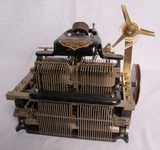
L.DOIGNON CHARACTER PRINTER , 1880's The printer used Baudot's 5 bit code, using five telephone lines, to receive a signal that could be printed on a strip of paper. It was all driven by an electric motor. On receipt of a start signal the five bit code would latch five solenoids that would enable the mechanism to print a character by turning the wheel and engaging the correct letter. After printing a character the solenoids released ready for the next one. A0234 |

Larger image |
BLICKENSDERFER TELEPRINTER No 5, 1890 This machine has been converted to a Teleprinter from the famous No5 machine, hence no keyboard. Instead are 5 solenoids with linkages to decode the 5 bit code into text. The whole machine is driven by a pulley connected to an electric motor (not present). A0756 |

Larger image |
CARPENDIER PUNCH TAPE READER, 1890's Punch tape reader for five bit Baudot coded tape, as the tape is pulled through the trough five fingers are able to move upwards into the holes in the tape, contacts inside the unit detect this and pass on the information to other equipment. Be the first to write a comment about this objectA0235 |

Larger image |
DOUBLE PLATE SOUNDER, 1900's In the early days of Morse all railway stations were equipped with the new morse code technology. Hearing the clatter of a Morse receiver, known as a sounder, could be a problem in a noisy environment. A gentleman called Charles Bright invented 'Bright's Bells' in 1855, a crude version of the exampe shown here. A0227 |

Larger image |
POST OFFICE INKER No. 128, 1900's Inkers were used to print dots and dashes on to a strip of paper to enable easier reading; known also as a Direct Writer. This item uses a clockwork motor to drive the paper forward Be the first to write a comment about this objectA0242 |

Larger image |
ATM STOP START INKER, 1910's Morse Inker for recording dots and dashes on a strip of paper. A0243 |

Larger image |
NON-POLARISED MORSE SOUNDER, 1920's A simple Morse Sounder used for receiving Morse. It may have been made by Gamage who specialized in telegraphy equipment in the 1920's. Non polarized unit similar to a design used by the Post Office and purchased by those who wished to learn the 'Art' of Morse telegraphy. And indeed it was an art. Morse code requires very high skills, strange that when it became adopted as a standard for communication by Samuel Morse in 1844 many other simpler forms of sending characters by wire were being developed, and yet Morse surpassed them all, probably because of the desire to improve or own a skill that others could not achieve, in today's world skills are avoided by modern computing. It was possible for the operator to distinguish whether the arm of the unit was up or down, by the different sound as the spaces between the dot or dash identified the end of a character, spaces between words could also be given as larger gaps, but most skilled operators omit this and join all the words up, making it important to write down what is heard immediately to avoid confusion. Be the first to write a comment about this objectA0887 |

Larger image |
POST OFFICE POLARISED SOUNDER, 1890's Receiving instrument for Morse code, invented by CC Vyle in the late 1800's and in use until the 1960's. A0229 |

Larger image |
WHEATSTONE NEEDLE TELEGRAPHY STATION, 1930's In 1851, Samuel Morse and his code was accepted around the world. (See 'A brief History of Telegraphy' above) A1235 |

Larger image |
SINGLE NEEDLE TELEGRAPH (WHEATSTONE NEEDLE), 1930's Information can be read if a needle is moved to the left or right. The single needle unit was a further development of Wheatstone and Cookes 5 needle system, which did not use Morse Code, and was replaced by the single needle system. This unit is clearly marked with the complete alphabet in Morse code on its face, and was probably used by the British Post Office. View 1 comment about this objectA0228 |

Larger image |
RAF MORSE INKER, 1930's Morse inker which transferred Morse Code into dots and dashes printed onto a strip of paper. A0233 |

Larger image |
GPO NON-POLARISED 20 Ohm SOUNDER, 1930's Post Office Polarised Sounder A0803 |

Larger image |
CREED 7E TELEPRINTER of 1931 Frederick George Creed was born in Canada and spent the early part of his life working on Morse equipment. He was convinced he could do better. He then moved to Scotland and developed a method of sending messages by text. Later he formed Creed and Company Ltd, and in 1921 they were at Telegraph House East Croydon. A0936 |

Larger image |
CREED TELEGRAM TELEPRINTER 47B, 1950's Used in Post Offices throughout the world for typing Telegrams. The Creed model 7 page teleprinter, whilst not the first A0098 |

Larger image |
TIN CONTAINING ROLLS OF GUMMED TAPE, 1950's Paper tape used in telegraphy machines, such as the Creed 47B item NoA0098. Not to be confused with punch tape, the paper is too narrow for this, the gum is used to stick it to the Telegram sheet. As it says on the tin! Be the first to write a comment about this objectA0531 |
Further Reading (external sites):
Back to top


